ASHRAE Housings

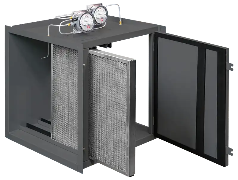
American Metal filter Company is proud to introduce the RaptorSeal Air Filter Housing line, or RSA, the ideal solution to standard ASHRAE housings, designed to allow immediate access to higher efficiency air filters for existing applications and new construction projects.
The RaptorSeal line of products was developed in response to the global pandemic that underscored that current air exchanges and air filter efficiencies were grossly inadequate. Overnight, air filtration was no longer a maintenance expense, rather it became a critical, and potentially lifesaving, requirement for the health, safety, and well-being of building occupants.
AMFCO committed to developing the RaptorSeal line to provide the most customizable and fastest source for these air filter housings to meet the current market demands.
“Worldwide supply chain issues, the lack of aluminum ingot, and raw material cost inflation forced us to be conservative with our RaptorSeal designs, and to provide you only what you need. Period. These obstacles made it clear that the traditional Air Filter Housings needed an overhaul. Instead of making a one-size-fits-all product where you must adjust your requirements to meet our offering, the RaptorSeal Air Filter Housing line provides you with the exact hardware to complete your system with the best design and the least amount of hardware; quickly, accurately, and economically.
We look forward to working with you.”
– Val C. Deilgat, President
*A note about magnahelic gauges. Gauges may be used to measure the pressure drop across each filter contained in a housing, or to measure the pressure drop across the entire filter pack. The customer service team at American Metal Filter Company will communicate with you to make sure we are monitoring the correct air filter(s) when gauges are selected.
Refer to instruction steps 1-5 below to create a RaptorSeal Air Filter Housing to meet your specific application. Use the downloadable pdf below to fill out your order. Before We Begin – The Left or Right side of a housing is determined by facing the air entrance side of the housing. Here We Go!
1. Housing Dimensions and Airflow Capacities in CFM
- For New Construction Applications: The overall height and width of the housing is determined by the operating CFM required for the application. Please note there are 72 various housing configurations to choose from, yet many of them have similar CFM capacities, i.e., a 6,000 CFM housing is available as a 05H60W, 10H30W, 15H20W, 20H15W, or 30H10W.
- Choose the CFM airflow capacity (or capacities) from Selection Chart No. 1 that meet the application requirements.
- If only one CFM capacity is available, draw circles around the CFM and the corresponding Height and Width Codes.
- If more than one CFM capacity is available, decide which overall height and width dimensions are best suited to the application, and draw circles around the CFM and the corresponding Height and Width Codes.
- For Retrofit Applications: The existing plenum dimensions determine the overall height and width dimensions of the housing and the resulting total CFM available at 500 FPM.
- Choose the Height and Width dimensions from Selection Chart No. 1 that fits the existing plenum opening.
- Draw circles around the corresponding Height and Width Codes corresponding to the dimensions.
- Draw a circle around the resulting CFM located at the intersection of the Height and Width Codes.
2. Housing Location and Air Filter Specifications
- Place an “X” or a checkmark next to the location of the housing. The choices are Indoor or Outdoor.
- It is critical that the Air Filter Specifications are filled out completely.
- POS – Position of filter is stated as a number to identify the placement of the air filters, with the No. 1 position located at the air entrance side of the housing.
- CODE – The following codes identify the function of the air filters and help determine magnahelic gauge location. They are PRE (prefilter), INT (intermediate filter), or FIN (final filter)
- Air Filter Dimensions are described by H X W X D using nominal dimensions. When full and half size air filters are used, provide both sizes i.e., 24 X 24 X 4 / 12 X 24 X 4. When describing a headered air filter, include the overall depth of the filter including the header.
- HEADER – Answer Yes or No to describe filters with or without headers.
- INITIAL PD and FINAL PD – Initial and final pressure drop values, measured in water column (w.c.), are critical to ensure the housing meets the application requirements. Furthermore, the FINAL PD determines the correct pressure drop range for the magnahelic gauge.
- GAUGE* – Answer Yes or No for each filter that requires pressure drop monitoring.
3. Standard Options
Please note: the following five selections help make the housing part number. For each component, place an “X” or a checkmark next to the appropriate choice in the accompanying fillable pdf download.
-
- MATERIAL ALLOY
- FINISH
- DOORS
- INSULATION
- GAUGES
4. How to Determine Housing Depth
Conventions – Remember, RaptorSeal Air Filter Housings may be manufactured to any depth required, and this provides the design flexibility to create the best fitting, highest performing air filter housing for the application. The following design conventions describe the available choices to consider when creating a housing.
- The air entrance and air exit corner uprights are 3.00” deep.
- A 1.00” space between air filters is recommended when no magnahelic gauges are required.
- A 3.00” space between air filters is required to install a pitot tube when magnahelic gauges are specified.
- 1”, 2”, 4” and 6” thick nominal filters require a track depth of the same dimension specified using a whole number.
- A headered filter, while it requires a 1” deep track, must be identified by its overall depth to determine the total housing depth.
Depth Sizing – Determine the depth of the housing by applying the conventions above. Refer to the three samples on the Submittal Drawing to determine the minimum depth required based upon the air filter selection and magnahelic gauge requirements.
- Sample No. 1 – Holds a 12” deep headered filter and uses one magnahelic gauge. The housing depth = 18” (See illus. No. 1). The housing depth includes 6” for the uprights and 12” for the headered air filter for a total of 18”.
- Sample No. 2 – Holds a 2” prefilter, a 12” deep headered filter, and does not use a magnahelic gauge. The housing depth = 21” (See illus. No. 2). The housing depth includes 6” for the uprights, 2” for the prefilter, 1” for the space between filters (no magnahelic gauge), and 12” for the headered air filter. The housing depth = 21”.
- Sample No. 3 – Holds a 2” prefilter, a 4” secondary filter, and a 6” final filter, and uses 3 magnahelic gauges to monitor the pressure drop of each air filter. The housing depth = 24” (See illus. No. 3). The housing depth includes 6” for the uprights, 2” for the prefilter, 4” for the secondary air filter, 6” for the final filter and 2 X 3” for the spaces between the PRE and INT air filters and INT and FIN air filters. The housing depth = 24”.
